VTube-LASER Intersection Point Tolerances
The Limitations of Using XYZ Intersection Point Deviations to Qualify a Part Shape
Before describing the intersection point tolerances, it is essential to note that XYZ tangent points (read about them on this page) are preferred for tube shape qualification. Intersection points are not as good as tangent points for tube shape qualification.
Large bend angle shapes |
Large bend angle shapes, for example, exaggerate deviation because they are far from the space of the tube surface. As they move away from the tube, the intersection deviation grows as well. The higher the bend angle at an intersection, the further the intersection points are from the actual part - which means that, as the bend angles increase, the deviation exaggeration grows. Tangent points don't have this problem because they are always closely connected to the straight sections of the tube shape. See a visual example below where the intersection deviation is 6 times the tangent point deviation. |
Shallow (small) angle bend shapes |
These have a different kind of deviation exaggeration. The nearly parallel centerlines make it very difficult for computer math to repeat the location of the intersection along the axis of the centerlines. The reason is because very small locations in centerline location will cause large swings in the point placement. This is true regardless of how accurate the measuring system is. |
The same intersection tolerance can have a different meaning depending on the part shape. |
The core problem is that, when using XYZ intersections to qualify the tube shape, the same value for tolerance has a different meaning as the part shape changes. Intersection deviations tend to exaggerate the deviations mathematically for both small-angle and large-angle bends. |
Read about centerline tangent point tolerances.
A Visual Example of the Problem With A Bend Angle That Approaches 180-degrees
See these two images to help understand the problem with using intersection points for qualification.
The two tangents show 0.054 and 0.046 inches in deviation. However, the intersection points are separated by 0.322 inches.
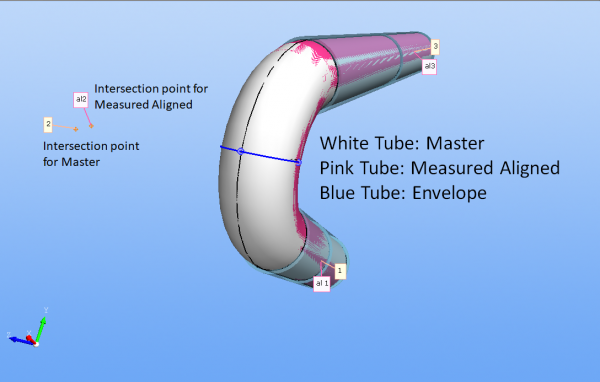
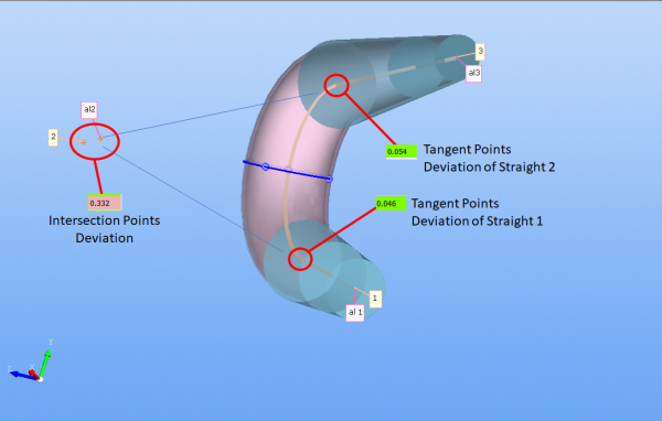
In this case, the intersection deviation is 6 times larger than the profile deviation of the tube. However, it is easy to see that the part falls well within the functional envelope (the transparent blue cylinders) that are formed by the tangent deviations. Intersection deviations do not act as a good representative of the actual profile deviation.
Why Include Intersection Deviations in the VTube Interface?
The only reason we include intersection point deviations in reports because a customers requires them for part qualification.
How the XYZ Intersection Deviation Tolerances Work
|
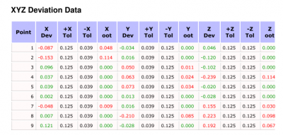
The XYZ intersection deviation tolerances allow you to quickly qualify a part using +/- tolerances to the intersection points. The intersection tolerances are based on values are that follow the three axes in a coordinate system. Since the tolerances measure along the axes, these tolerances can be positive or negative to also indicate a direction. |
|
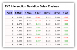
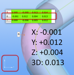
XYZ Intersection DeviationsThe XYZ intersection deviation tolerances are compared to the XYZ deviations as shown in the model in this screen image. What are 3D Deviations?The 0.013" value is the straight-line distance measured directly from the master to the corresponding measured points. |
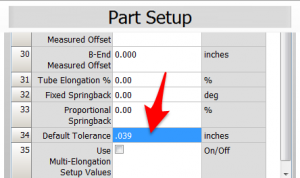
Set the Default Tolerance in Part Setup Menu
You can set the default tolerance in the Part Setup menu. Scroll down to row 34. |
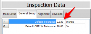
Set the Default Tolerance in General Setup Menu
You can set the default tolerance in the Inspection Data General Setup menu. (This is for version 2.5 and newer.) |
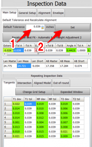
Set the Default Tolerance in Inspection Data Menu
You can set the default tolerance in the Inspection Data menu by entering a Default Tolerance at the top and pressing the Set button. |
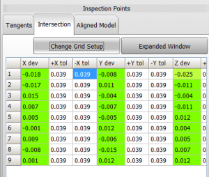
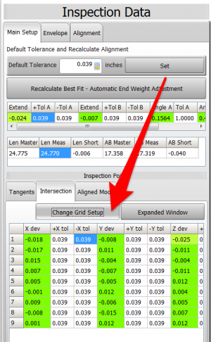
Set the Tolerances in Inspection Data Grids
Click on the Change Grid Setup button until you see the tolerances in the grid. |
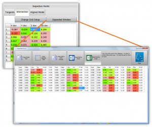
Set the Tolerances in Expanded Windows
The second place to edit the value is in the VTube-LASER Expanded Window. Click on the Expanded Window button to display the Expanded Window, then change the tolerances there. The benefit of the Expanded Window is that you can view all the tolerances simultaneously. |
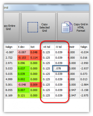
Setting All The Tolerances At The Same Time
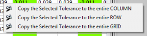
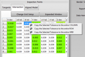
Using a popup menu, the intersection deviation grids allow you to set the default tolerance to every value in a row, column, or entire grid. To use this feature, single-click on a tolerance value, then right-click and choose the action in the popup menu. |
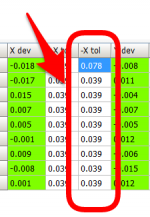
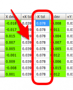
The screen images on the right show an example of before and after changes made to an entire column: |
|
XYZ Intersection +/- Tolerance Values in Printed Reports
|
The XYZ Intersection deviation values can be included in reports:
|