VTube Reverse Calc from MIL-D-9898C Absolute Bender Data to Centerline XYZ Data (Conrac)
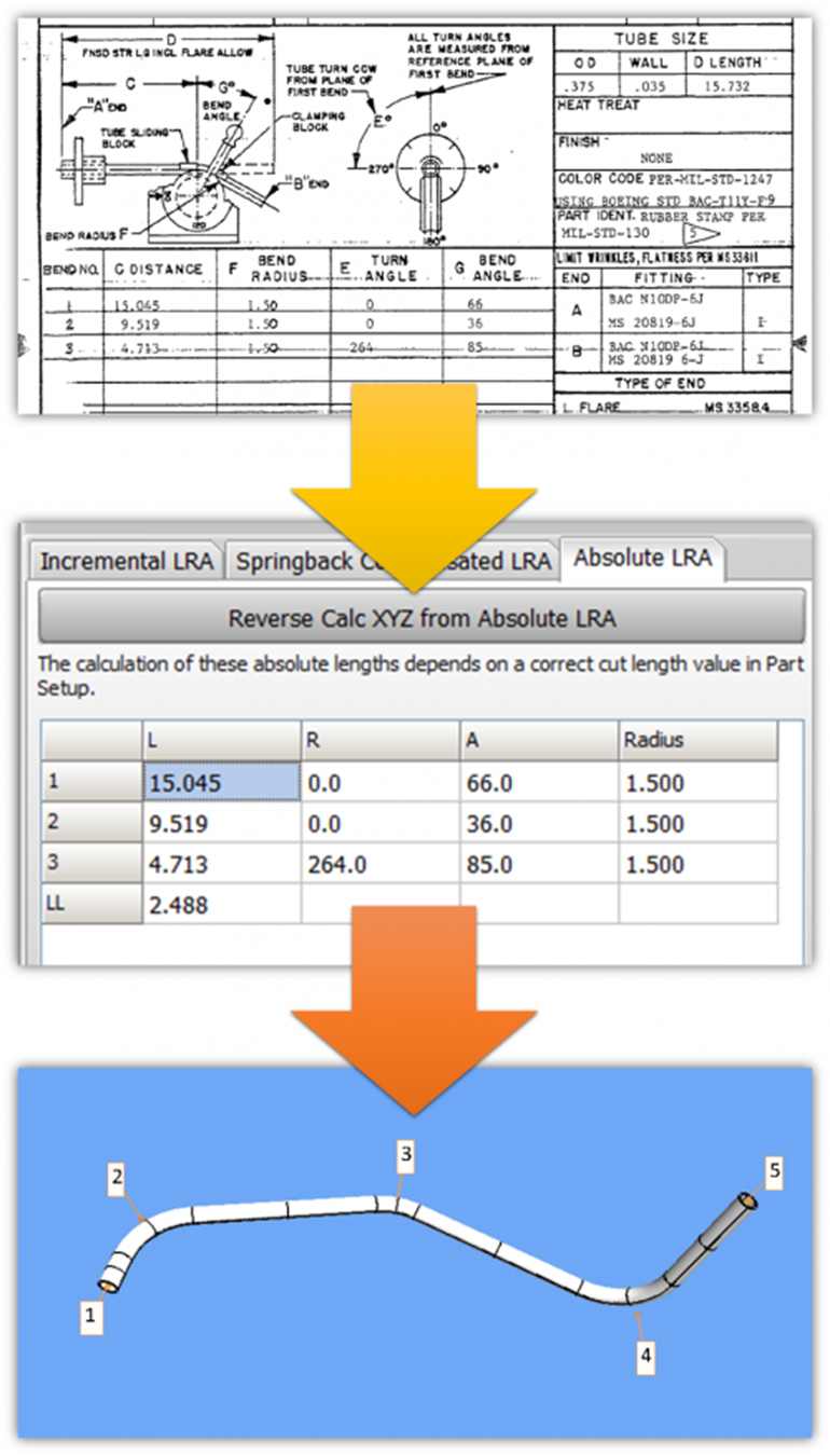
VTube-STEP and VTube-LASER can convert this military spec bender chart data into the LRA grid section of the Part Data menu. This specification was created decades ago when the US Air Force preferred CONRAC benders. According to NOTICE 1, it was made inactive on January 21, 1986. No new designs are created with this spec. CONRAC benders have been obsolete for decades, but legacy tube shape data is still stored with this specification.
General Principals for the Specification
ABSOLUTE LENGTHS
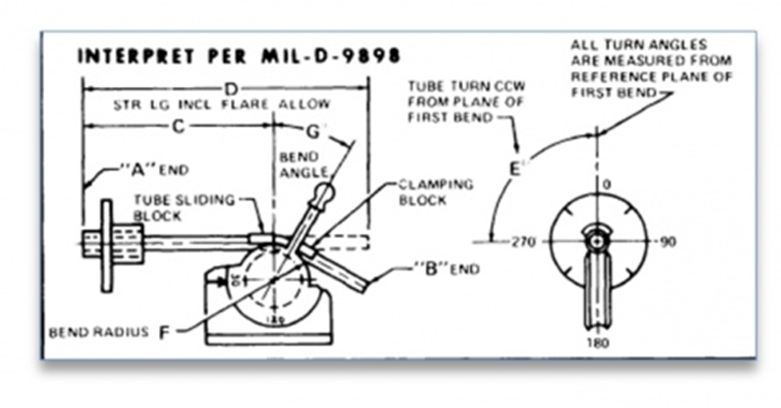
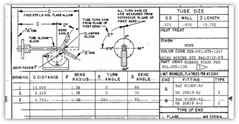
This bender data spec uses ABSOLUTE LENGTHS between bends as if derived from a tape measure attached to the Feed axis of a bender. CONRAC benders sometimes had tape measures riveted along the rail of the carriage that moved along the length of the bender. The lengths indicate where each bend begins.

ABSOLUTE ROTATIONS
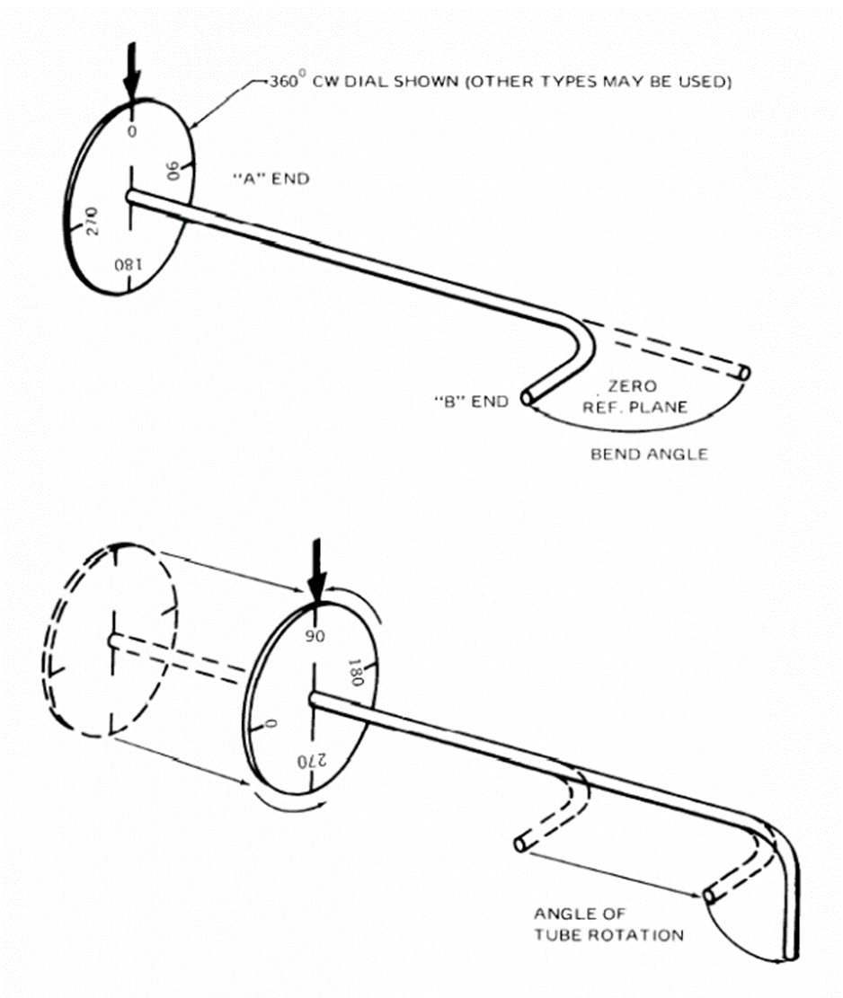
According to the spec, the bender data uses ABSOLUTE ROTATION data (twist angle between the planes of the bends). It is absolute because it always depends on the rotations in all preceding bends accumulated. The dial on an absolute rotation spindle reads from 0 to 360.
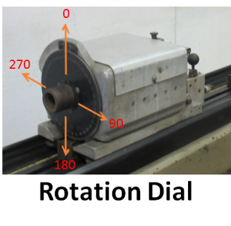
If a rotation does not change from one bend to the next, the rotation value remains at the degree position it was at in the previous bend. For example, if a rotation is at 270 degrees, and the next bend has no rotation relative to this bend, the rotation dial stays at 270 for the next bend. Every rotation value depends on the proceeding rotation values. This is why it is referred to as "absolute."
DRAW BENDING
Although it can be ambiguous in the specification, most of the part data from this specification assumes DRAW bending versus COMPRESSION bending - which means the LENGTH values move the carriage so that the tube is positioned at the start of each bend (for clamping and drawing around the bend die that rotates with the bend arm) rather than the end of each bend (for clamping with rollers or wipers and compressing around the bend die that does not rotate with the bend arm).
However, there are cases where the spec can switch to compression bending. Switching between the two types of bending causes the length or stop values to change. For draw bending, the stop is positioned at the start of the arc length of a bend. For compression bending, the stop is positioned at the end of the arc length of the bend. VTube allows for input of either type of data. Absolute 1 style is DRAW. Absolute 2 style is COMPRESSION.
VTube Absolute LRA Data Rules
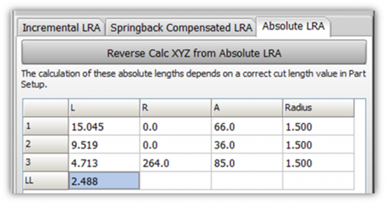
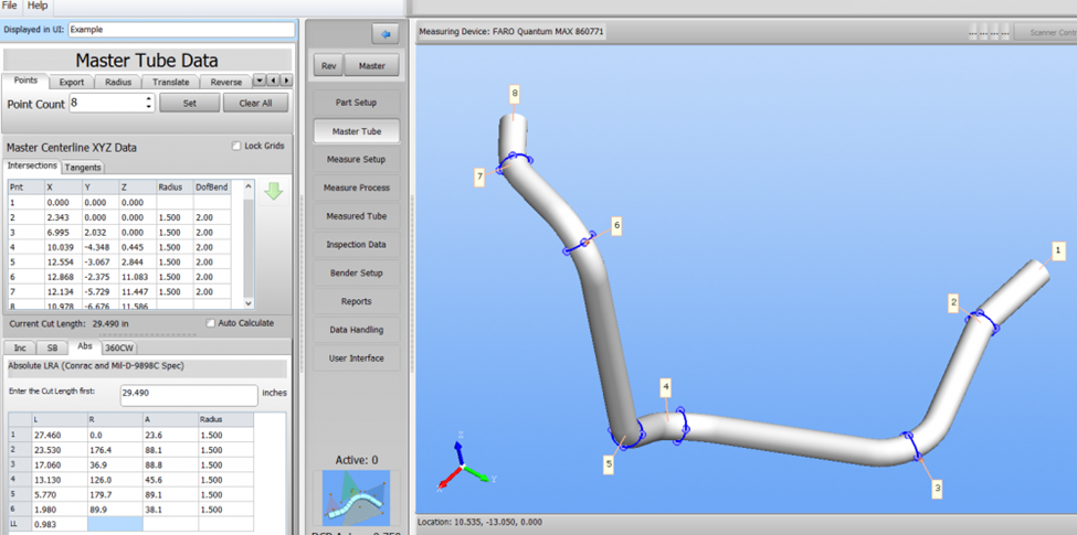
The Absolute LRA grids are in both STEP and LASER modes of VTube. They are automatically calculated when you import a model or enter centerline XYZ data.
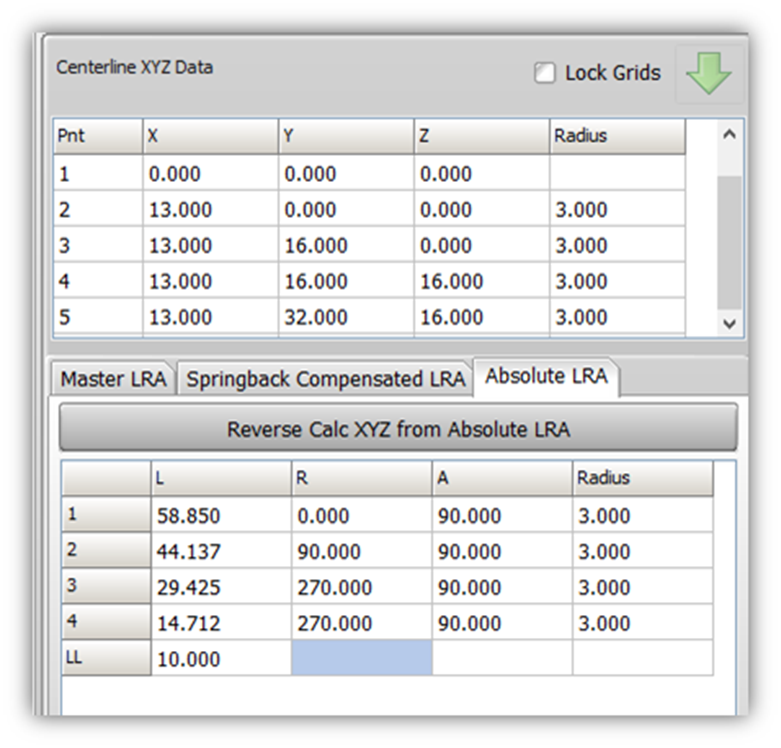
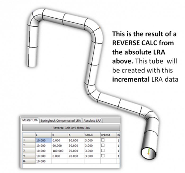
You can Reverse Calc to XYZ data from Absolute LRA data by entering data in the Absolute LRA grids in either VTube-STEP or VTube-LASER.
The LAST length value is always the actual length of the last straight of the tube. So, this value has a different meaning than the rest of the L values in this grid.
All other lengths should progress from larger values at the top of the grid and decrease as you move down the grid.
None of the lengths should be larger than the Cut Length - or negative incremental length values may be calculated.
The rotation values are always between 0 to 360 degrees.
If you enter a negative rotation value, it will automatically be converted to its equivalent in the 360 range when you reverse calc. For example, -45 degrees will be converted to +315 degrees (360 + -45).
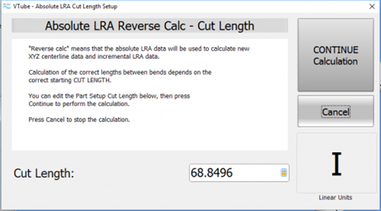
Reverse Calc with Absolute LRA Data Requires a Predetermined Actual Cut Length
Reverse calculation requires a predetermined actual cut length, so this dialog will display to allow you to enter a correct Cut Length before VTube finishes the calculation. This Cut Length value will overwrite the value in the Part Setup menu. Remember that the Cut Length value should be a larger value than the largest LENGTH value in the Absolute LRA grid
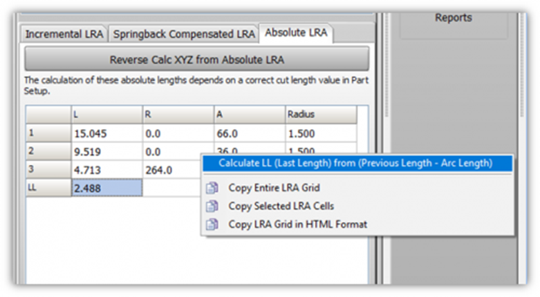
Calculating the Last Length "LL" value
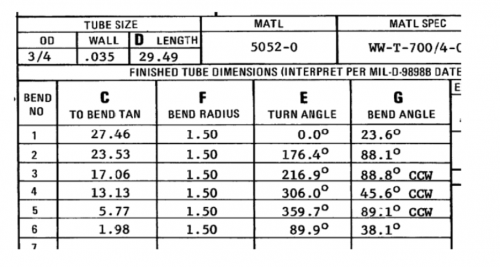
Notice in the MIL-D-9898C bender chart that there is no LAST LENGTH value. However, VTube includes an LL (Last Length) value in the last row.
You can only calculate the LL value using a popup menu for the Absolute LRA grid.
Rules for calculation:
• 1 - The LENGTH value in the preceding row must already be entered.
• 2 - The BEND ANGLE in the preceding row must already be entered.
• 3 - The RADIUS value in the preceding row must already be entered.
If these three conditions are true, you can use this feature to calculate the LL value in this chart accurately.
Example of Switching from CW to CCW Bend Angles
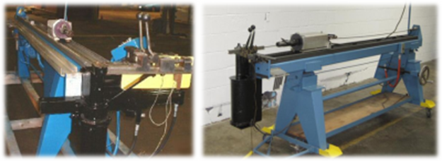
This bender protocol assumes CLOCKWISE as the default bending direction. However, sometimes, the part designer creates a tube shape where the bend hand changes from CW to CCW in the middle of the part. See the changing of bend hands in the two images below.
- The image with the blue arrow shows the standard CW bending.
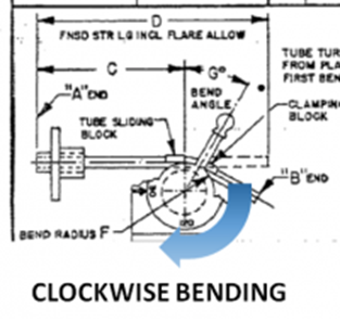
- The image with the yellow arrow shows CCW bending.
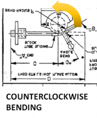
Changing from left to right or right to left bending changes the rotation plane by 180 degrees inside VTube.
So here are some rules to follow in converting the rotation data to be compatible with VTube:
Rule Idea |
Rule Explanation |
Add or Subtract 180 to the Rotation if the Bend Hand Changes to CCW |
The rotation at that bend must change by 180 degrees to take the bend plane direction change into account. |
Valid Rotation Value Range |
The rotations for this protocol are based on a 0 to 359.99-degree dial. Rotations are always a positive number in that range. Whether you add or subtract 180 depends on which method (adding or subtracting) gets you a positive number inside the valid positive range. (The only time rotations exceed 360 is for coiled parts - which is a special case for this protocol.) |
Propagate Rotation Changes |
When the bend hand changes to CCW, it is necessary also to change all following CCW bend rotations by 180 degrees. |
Propagation Stops When... |
However, the propagation of changes must stop when you come to a bend that switches back to CW. So, in the example case below, the last rotation is never changed. |
|
Show an example of how to use the rules above:
|
Entering Absolute LRA into VTube
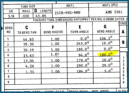
Entering Absolute LRA into VTube with a 180-degree (Split) bend.
If you have an absolute data grid with a 180-degree bend, you will need to use the Split Bend feature inside VTube.
How to Enter Incremental Rotations from a MIL-D-9898C Type Bender Chart in VTube-STEP
STEP 1 - Enter the Part Setup values (Part Number, Diameter, default Centerline Radius, etc.)
STEP 2 - Change to the Parametric Tube Data menu in the navigation pane.
STEP 3 - Enter the Points tab menu. Enter the number of points, including end points and intersection points. (For example, a 6-point tube has five straights and four bends.)
STEP 3 - Enter the Abs-Draw tab menu (lower left) and enter the Cut Length.
STEP 4 - Enter the C Distances (click on the first cell and enter data) from top to bottom. The final C distance is always the final leg length that is calculated for you.
STEP 5 - Skip the F Turn Angle column and click on the first cell in the G Bend Angle column. Enter all the bend radii. Leave the rotations at ZERO for now.
STEP 6 - Move left to change to the Inc tab menu and enter only the incremental rotations.
STEP 7 - Press F2 and F3 to redraw and zoom all.