How to Measure a Cope Angle in a Tube
This article discusses how to measure coping and the tube shape in VTube-LASER. The method measures the coping as if it were an additional straight on the end of the tube. In this method, an adapter pipe that joins the main pipe at the coping can be treated like an extra end-straight on the pipe in VTube-LASER.
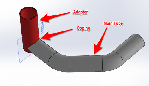
STEP 1: Design a Coping Adapter in a Solid Modelling Program
In this example, we designed an adapter in SOLIDWORKS that simulates the joining pipe to the main pipe. |
|
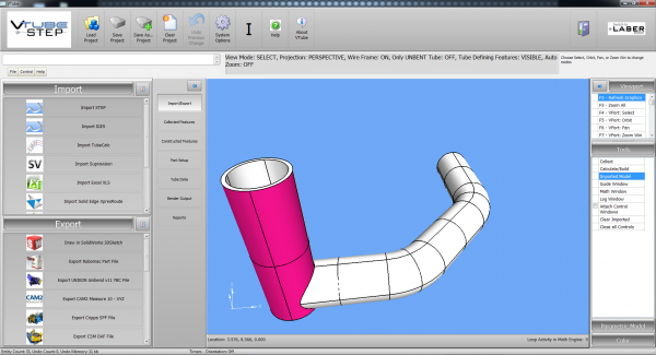
STEP 2: Import the Model with the Adapter into VTube-STEP
Every VTube-LASER includes VTube-STEP as a mode. Switch to STEP mode, clear the project, and import the STEP model created in the solid modelling program. |
|
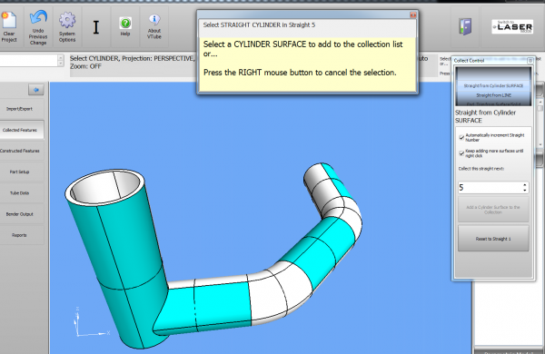
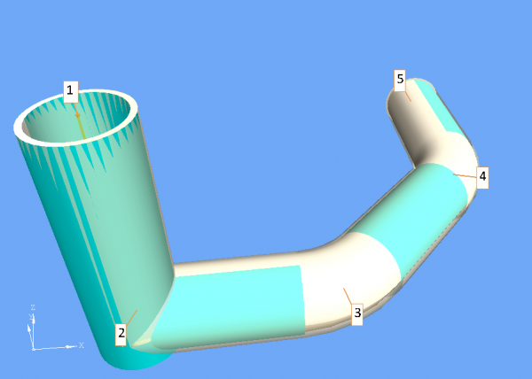
STEP 3: Collect the Surfaces with the Adapter in VTube-STEP
Use the Collect feature to build a collection of cylinder surfaces. Include the adapter as the end straight. |
|
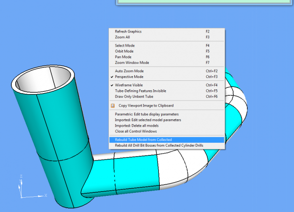
STEP 4: Rebuild the Model in VTube-STEP
Right click and rebuild the model. |
|
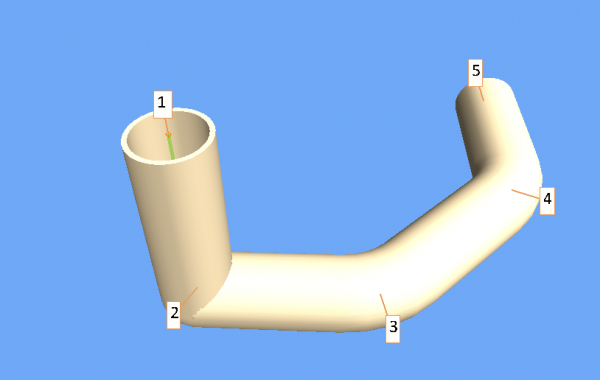
STEP 5: Confirm the Parametric Model in VTube-STEP
You can now confirm the new parametric model (the model that is controlled by new XYZ coordinates) by pressing F9 to turn on and view the point labels. |
|
STEP 6: Switch to VTube-LASER Mode and Measure the Part
Switch to VTube-LASER, attach the adapter (temporarily) to the coping on the part, then measure and qualify the entire part with the adapter. |
|
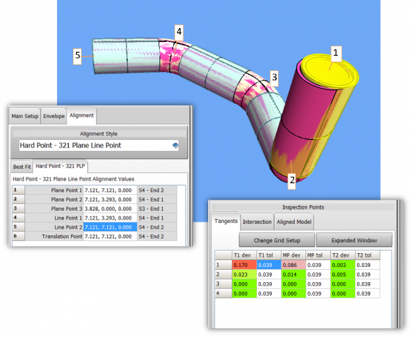
STEP 7: Setup and Align the Measured Part
In this alignment, we used 321 Plane Line Point alignment to lock the tube to itself, and allow all the error to float to the coping end of the tube. |
|
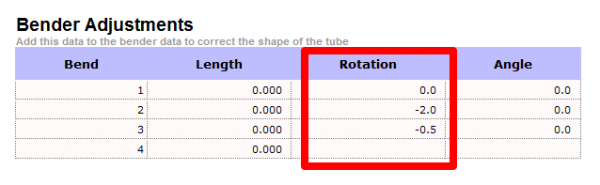
STEP 8: Get the Rotational Adjustment
You can also print out a Bender Corrections Only report to see the exact rotational adjusting to make to the part when cutting the coping. |
|