GD&T Basics - Geometric Dimensioning and Tolerancing Concepts
Key Concept: Dimensioning and Tolerancing are different concepts for GD&T.
1 - Dimensioning: How to dimension a part design
Dimensioning controls part design.
Dimensioning is represented by standard dimensions to "features" around the part.
2 - Tolerancing: How to create a tolerance for a part
However, dimensions in GD&T do not control tolerance values. Tolerances are set separately by referring to geometric characteristics called "features." A feature tolerance can be set as a form ("Is the shape good?"), orientation ("How parallel?"), position ("Where is it in space?"), or runout (a combination of features referencing multiple tolerance types simultaneously).
For example, a common geometric characteristic or feature is position.
| This is the position symbol. |

The position feature lets designers set the tolerance for deviation from the true position of a feature in the part. The tolerance for a position is called a "position tolerance."
Key Concept: FEATURES are Toleranced in GD&T - not Dimensions
A key concept is that GD&T always tolerances to features, rather than tolerancing the dimensions.
Key Concept: What is a FEATURE?
From page 4 of ASME Y14.5.1-2019: "Per ASME Y14.5-2009 feature: a physical portion of a part, such as a surface, pin hole, or slot, or its representation on drawings, models, or digital data files."
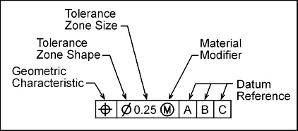
Key Concept: FEATURE CONTROL FRAME
A feature control frame is the ASME-approved rectangular frame with symbols that control the tolerancing for geometric features. The ISO term is "Tolerance Indicator." In the USA, the most common term is "Feature Control Frame."
| This is a feature control frame. |