About Benderlink Ethernet Modules - Long Distance Communications

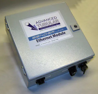
There are two types of Benderlink Ethernet modules. Both modules allow for long-distance communications.
THREE BENDERLINK ETHERNET MODULE TYPES
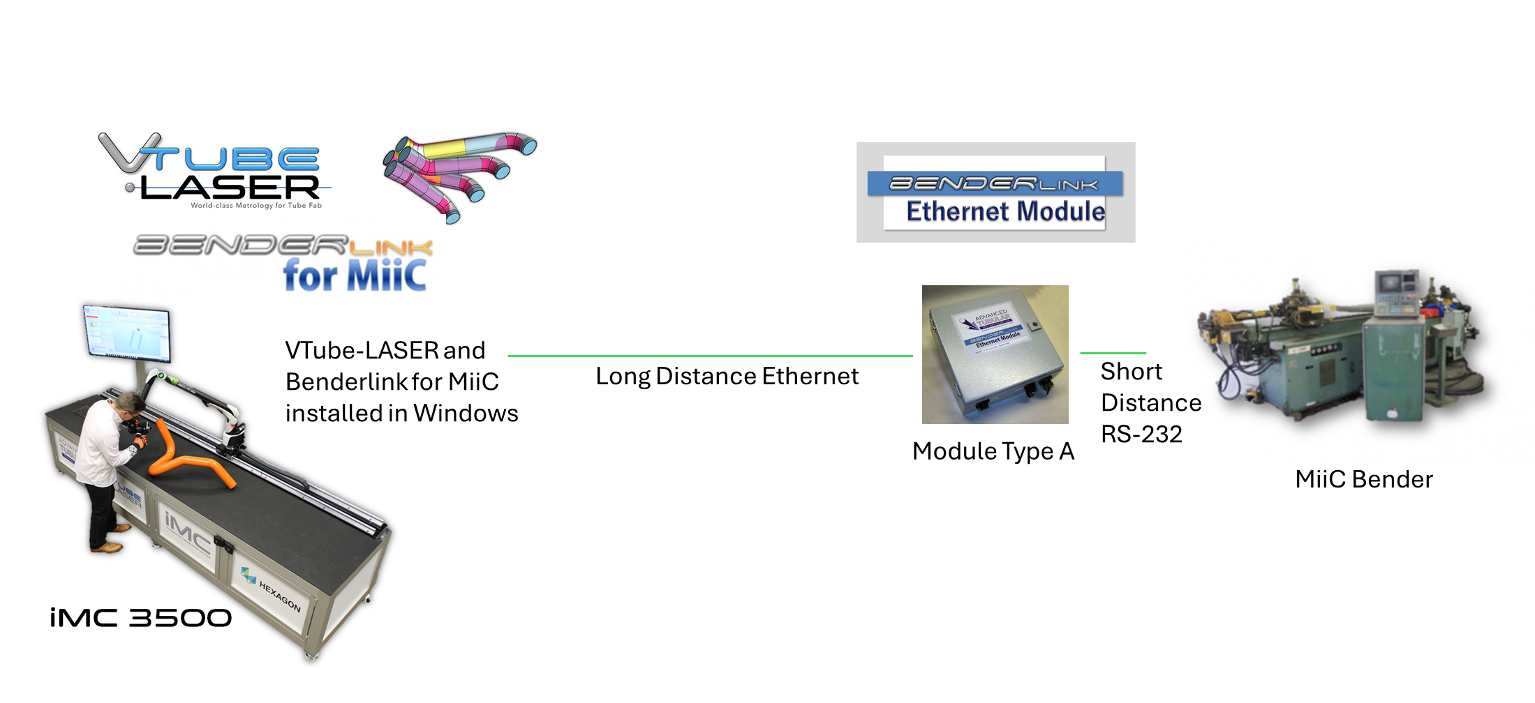
Module Type A - Benderlink Ethernet Module for RS-232
These modules are designed to allow long-distance communications for benders that use the RS-232 interface. Examples include CHIYODA, KEINS, and MiiC benders.

Module Type B - Benderlink Ethernet Module for Eaton Leonard Bender
These modules are designed to allow long-distance communications for Eaton Leonard benders. One module is placed at each Eaton Leonard Priemer, EL2000, or Velog Bender. These modules are then connected by Ethernet cable through a network to VTube-LASER.

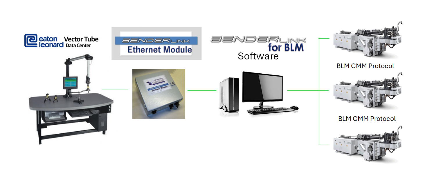
Module Type C - Benderlink Ethernet Module for Eaton Leonard VECTOR Measuring Centers
These modules allow long-distance communications between Eaton Leonard VECTOR LASERVISION measuring centers and non-Eaton Leonard benders. One module is placed at the VECTOR LASERVISION, connected to the Vector, and then an Ethernet cable is run to an adjacent Benderlink computer. Examples include BLM, CRIPPA, Pines, SMT Benders, etc.

TECHNICAL ASSISTANCE
- We include remote support to help with installing these modules on each bender. The support also includes Windows driver setup assistance.
- Each Benderlink Ethernet Module is typically attached to or placed near its bender wherever the communications port is found.
- The modules require a standard network infrastructure for connection to the VTube computer. This infrastructure can be wired or wireless, but we recommend wired. Please provide the network infrastructure necessary to connect the VTube computer and the benders. This includes terminated cables and switches in a standard Ethernet network that your company will purchase and install before our technician arrives for setup and training.
- These modules do not include any software necessary to handle the proprietary communications. The modules are designed to enable the electronic connection only. The communications protocol is the responsibility of VTube-LASER.
- We ask that you agree to assign qualified workers from your team to install the modules on the benders following our instructions. Your staff will be drilling and bolting metal to attach the boxes. They will bring 120vac to the back of each bender and connect wires to the modules. Our technicians do not carry any tools necessary to handle this work.
- Installing the modules before our technician arrives is a good idea to prevent any possible delays in the training.
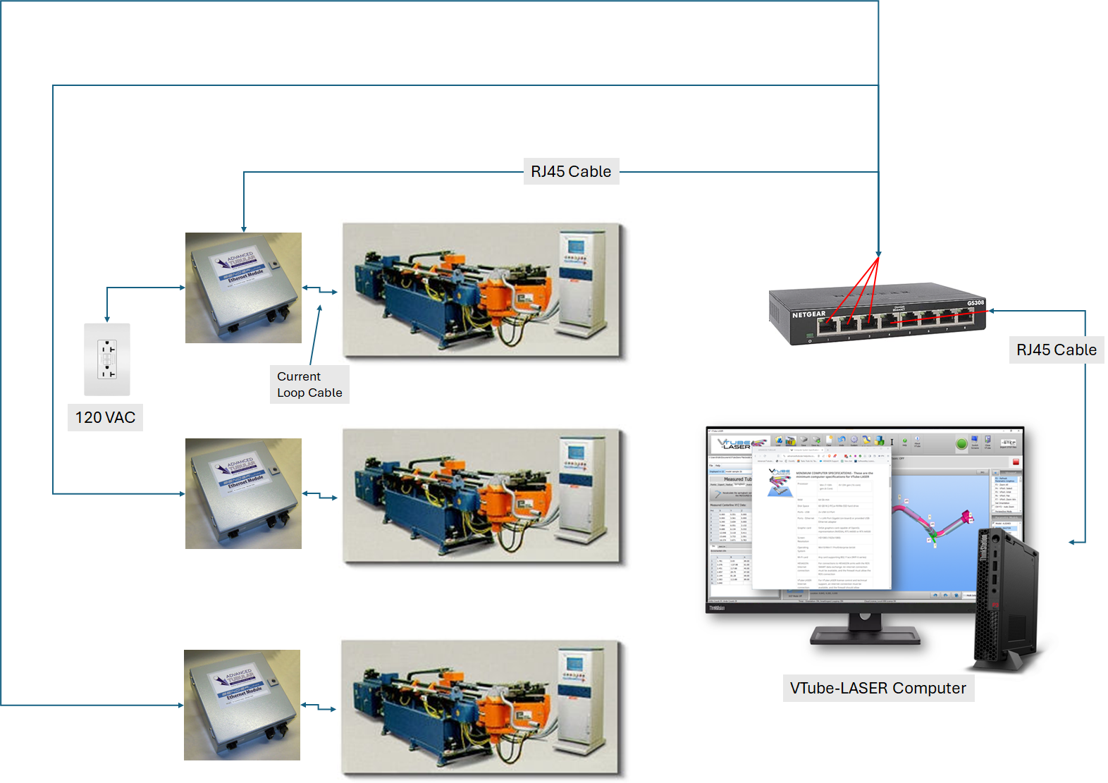
Typical Installation Diagram for Eaton Leonard Benders
- This is a typical diagram of how three modules would be installed to three Eaton Leonard Premier benders.
- The maximum ethernet cable length between any two parts of the diagram below is 100 meters (328 feet). Shorter cables provide better/faster connections.
- Each module will need 120 VAC power. We will supply the power cable with the module.
- We ask that you supply a powered outlet near the module.
- We supply the current loop cable that runs between the module and the bender port.
How to Install the TCP/IP Connection to a Benderlink Ethernet Module
- See this page to learn how MOXA NPort devices work inside the Benderlink Ethernet Modules:
https://advancedtubular.helpsite.com/articles/124264-how-moxa-nport-serial-device-servers-work-in-benderlink-ethernet-modules - For a high-level driver setup from a Windows computer, you can use the steps on this page:
https://advancedtubular.helpsite.com/articles/121177-how-to-install-a-moxa-nport-device-driver-in-a-windows-computer (For most installations, we recommend that you follow the steps in the driver page above. The direct connection page below is a lower-level way to make a direct connection to the NPort device using a web browser.) - For configuration from a web browser, you can follow the steps on this page:
https://advancedtubular.helpsite.com/articles/124263-managing-moxa-nport-serial-device-servers-with-a-web-browser
WARRANTY
- We have a high success rate with these modules because we fully test them for flawless electronic continuity before they ship. However, we cannot guarantee that the benders will always allow for flawless communications or that the software that controls communications will always be flawless in its handling of the legacy EL protocol.
- The Benderlink modules are built to order. Therefore, the purchase is non-refundable.
